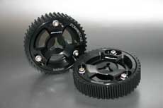
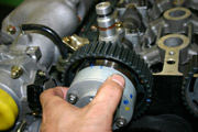
Maruha’s slide cam pulley.
It is typical to adjust the valve timing using a sliding pulley like this.
The valve timing’s adjustment and/or verification are indispensable during the engine’s manufacturing process.
This time we tried to summarize the valve timing’s basics.
The valve timing is being adjusted by the slide cam pulley, the genuine pulley etc. At this time it is possible to make the valve timing advance or retard. But what does this mean in reality?
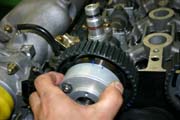
Maruha’s slide cam pulley.
It is typical to adjust the valve timing using a sliding pulley like this.
The Miata/MX-5’s B6 and BP engines are DOHC-types (double camshaft).
The crankshaft and the camshaft (IN・EX) are connected by the timing belt.
The 4-stroke engine repeats intake – compression – combustion – exhaust. This means that the crank rotates 2 times. The cam with 1 rotation is responsible for the intake and exhaust.
So the crankshaft with 2 rotations and the camshaft with 1 rotation gives the gear ratio.
We recommend the exchange of the timing belt after 100.000km. The reason for this is that the belt might break and the crankshaft and camshaft’s position changes and the engine stops. In some other cases the piston might hit the valves and cause big damage.
If we want to explain valve timing in an easy way, we can say that it is the timing of the opening and closing of the valve.
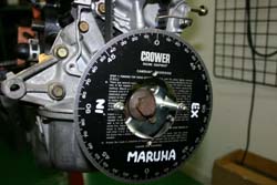
We set up a protractor at the crank and detect the piston’s position.
If the cam angle is the same, then even if we change the valve timing, the valve’s opening will happen at the same time.
Using the slide pulley we can adjust this timing.
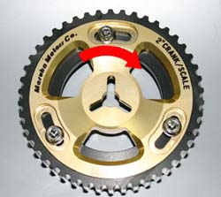
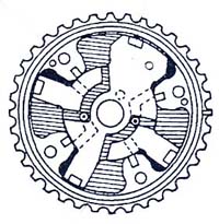
When we turn the center disc to the right, we talk about “advance”.
The valve timing’s value on the IN side becomes smaller.
The valve timing’s value on the EX side becomes bigger.

When we turn the center disc to the left, we talk about “retard”.
The valve timing’s value on the IN side becomes bigger.
The valve timing’s value on the EX side becomes smaller.
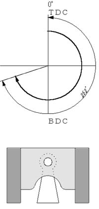
The basis is the piston’s position.
(for example a 252°cam)
The piston starts pushing the cam from TDC (0°), the piston starts the intake process and even though already passing through the BDC, the valve is still open. The valve closes at 72°after BDC. During this time the piston turns at 252°of crank angle.
Using the slide cam pulley we change the cam. Let’s suppose that it advanced 10°. This time the valve will start opening at 10°before TDC. The valve closes at 62°after BDC.
The valve starts opening at point A – before the piston’s TDC (crank angle 10°).
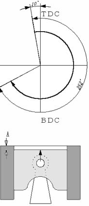
In both cases the cam is 252°, so the duration is the same. However, the valve timing changes.
In other words, we decide the cam’s position according to the piston’s position. To this we use the central angle.
The central angle and the highest lift angle show how the camshaft is being set in the engine.
Both express with a numerical value how the cam’s position is set, but both are a little bit different.
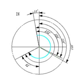
Taking the exhaust TDC (0°)on the IN side as base shows, how many degrees it takes to get to the cam duration’s center.
The 252°cam, that starts opening at 10°before TDC, closes at 62°. The half of 252°is 126°. However, if we count the 126th degree from the right, it becomes 116°. In other words, the central angle in this case is 116°.
If we use a 252°cam on the EX side and set the exhaust valve to open at 62°of BDC during combustion drop, then it will close at 10°of exhaust TDC.
The same as in the case of the IN side if we count from 0°of TDC (left turning), then we get a 116°central angle.
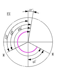
The overlap this time is 10°+ 10°= 20°.
Overlap signifies the state when both, the intake valve and exhaust valve are open.
Generally we use the 1mm lift method.
To the top of the lifter we put the dial gauge’s terminal, we rotate the crank and we use the time when it sinks 1mm to register the start and end of the crank angle count.
This 1mm becomes the measuring point and that’s why the crank angle is smaller than the cam duration.
The highest lift is the point when the camshaft opens (presses) the valve to the maximum. This position is being expressed by the piston’s position (crank angle).
If the camshaft is symmetrical, then the numerical value is the same as in the case of the center angle, but strangely there are lots of cases when it’s not true.
The reason for this is that there are cases when the camshaft’s profile is not symmetrical and the cam lobe is not sharp, so it is hard to get the highest lift’s position.
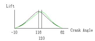
If we measure the opening and closing at 1mm lift and set the middle as the center angle, we get 116°. Under the same conditions if we measure it during the cam’s highest lift, we get 120°.
The numerical value shifts 4°, which can mean that for example the cam’s profile has to do something with it.
Let’s take a look at the graph above. In the case of the symmetrical cam the black line expresses the crank angle and the cam lift’s relation.
If it is an asymmetric cam, then the crank angle and the cam lift’s relation is being expressed by the green line.
We put the dial gauge’s terminal to the lifter’s top and measure the point when the cam lobe presses the lifter down the most.
The cam lobe is not sharp and the highest lift’s crank angle is in between the ranges of 6-8 degrees.
For this reason generally the highest lift – 3/100mm – is set as the standard and from there we calculate the highest lift point.
Even if there are lots of types of measurement methods, the most important point is to continue the work with the same method.
The professionals assemble many engines by their own method and collect data in their own way.
By repeating the same method, they compare the data and go on to the next step.
How do we set the camshaft?
The best is to raise the torque while securing idling and getting the highest power. However, all this is not that easy.
Maruha’s method is variable valve timing.
A hydraulic slide cam pulley is being set up, (in the case of Mazda it is being called “actuator”) and it controls the oil pressure electronically.
We strictly divide idling, low rpm, middle rpm, high rpm etc. and by repeating the valve timing’s advance and retard, we plan the most appropriate setup.
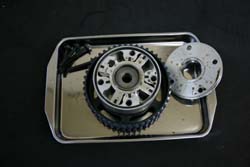
The disassembled actuator.
The actuator’s inner retard chamber is influenced by the oil pressure, and the rotor that is united with the cam rotates to the advancing direction.

Oil pressure influences the lag chamber of the actuator’s inside and the rotor that is united with the cam rotates in the retard direction.
Middle maintenance
Oil pressure influences both the advance and retard chamber and the position of the rotor that is united with the cam is being maintained.
Idling area and light load area
Making the overlap area smaller and lowering the amount of the combustion gases that enter the IN side. Thanks to this we can stabilize the rpm at idling and improve the fuel consumption rate. Furthermore, we can secure the engine’s stable performance in the light load area.
Middle load area
Making the overlap amount bigger, lowering the combustion temperature, lowering the NOX inside the exhaust gas. Furthermore, we let the not yet combusted gases combust to the maximum and lower the HC.
High load middle rpm
Make the closing of the intake valve faster , improving the middle rpm torque.
At low temperature
Set the overlap to the minimum, prevent the IN side from the entering of combustion gases. By this we can improve the fuel consumption rate and secure fast idling rpm.
At the time of engine start or stop
Minimizing the overlap amount, preventing the IN side from the entering combustion gases. By this we can improve startability.
The variable valve timing has a very complicated function and its setting is very difficult. But we hope that through this short report you got a better insight into it.
The cam is an item which is indispensable for engine tuning. Maruha keeping quality in mind, tries to provide all the necessary parts in a reasonable price. Feel free to contact us if you have any questions.
[home]